ZEISS CORRELATE
With ZEISS CORRELATE, you can analyze dynamic processes such as displacements, rotations or angle changes. Intuitive to use and equipped with practical functions, the software optimally supports you in your 3D testing applications.
Skip to main content


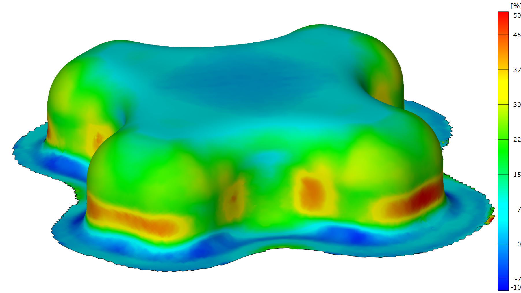
Forming analysis is a process to evaluate the forming states and surface strain levels of sheet metal components after press forming. Before forming, the raw sheet metal blanks are marked using electro-chemical etching or laser marking, either with a regular circle grid or a dot pattern. During the forming process, the circles or dots are deforming with the surface of the blank and thus changing their shape into ellipses. After the forming process, the diameters of the ellipses are measured manually or automatically to determine the minimum (minor strain) and maximum (major strain) strain behavior. The orientation of the major and minor strain describes the forming state of the local surface.
")
")
Surface strain values are compared after the measurement with the Forming Limit Curve (FLC – see the curves in the diagrams below) in the Forming Limit Diagram (FLD). The FLC is a material parameter dataset which describes the maximum formability in relation to the forming state of a sheet metal material.


Strain data values above the FLC are indicating overforming with a risk of failure of the sheet metal. If all data points are below the FLC, considering a certain safety margin, the forming process usually does not produce split parts.


Sheet metal forming analysis is mostly used in the automotive industry during the development process of sheet metal parts, for tool try-out and in production troubleshooting.
During the development process of sheet metal parts, the above explained forming analysis is used to validate numerical forming simulations and to determine overforming and unwanted flow of the sheet metal blank inside the press tool. Wrinkling and the trend towards cracking can additionally be determined and evaluated.
During tool try-out, the shape of forming tools is iteratively optimized to produce the correct component shape. The forming analysis is used to validate that the forming process stays inside the formability limits of the selected material.
If split parts are produced during series production, the forming analysis serves to understand and solve the underlying production problems. Comparing the measurement from the split part and the master part before production shows tool wear and material problems.


The forming analysis system ARGUS supports the optimization of the sheet metal forming process. For the automatic optical forming analysis, sheet metal blanks are marked with a regular dot pattern with 1 mm, 2 mm or 3 mm distance in between the dots, depending on the shape and radians of the part. After forming, the sheet metal component is recorded with the handheld ARGUS camera from different viewing angles. In all acquired images, 2D coordinates of all dots are mathematically derived and recalculated to 3D coordinates using photogrammetry principles.