
Correcting The CAD Data For Tools And Printed Components
Your challenge
Manufacturing production tools is a complex process: Even when simulation software is used, five, ten or even more iteration loops are often necessary to create a part with perfect fit. Tool correction requires not only in-depth knowledge of the part to be manufactured along with its specifications. The interactions of the individual adjustments must also be taken into account when tools are adapted. The same applies to 3D printing: The print result is influenced by a wide variety of parameters. CAD data for printed parts that are not dimensionally stable is often adapted by trial and error – a time-consuming and cost-intensive process.
Our solution
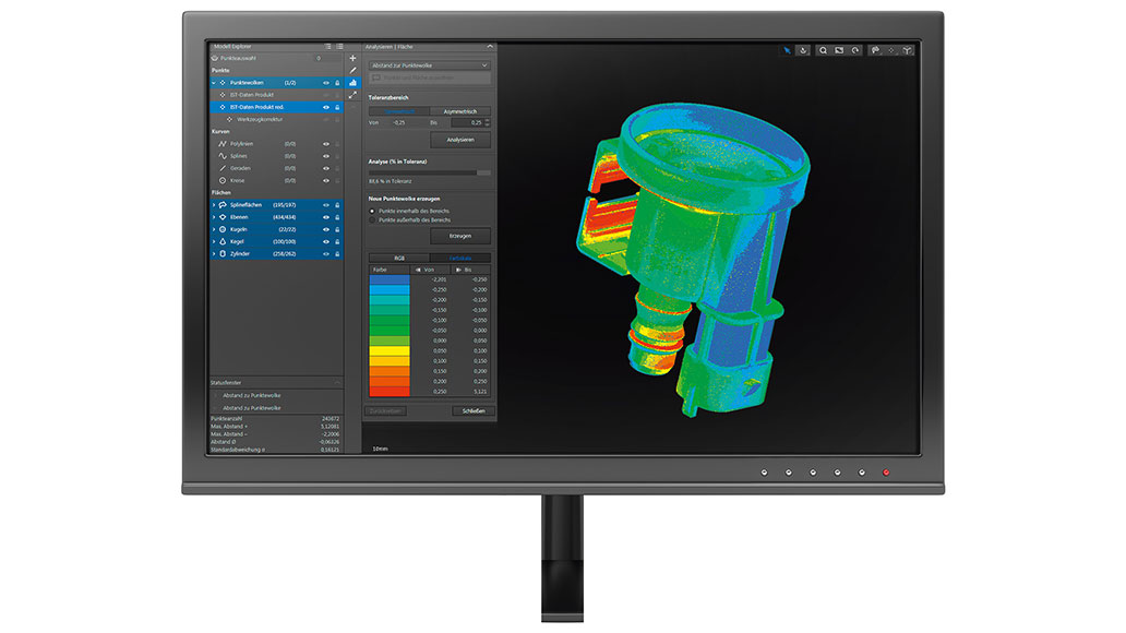
The ZEISS REVERSE ENGINEERING software reduces iteration loops in the tool correction process up to 50%. Simply import three data sets – the existing CAD data of the tool and the product as well as the real measurement data of the product – and then detect areas in need of correction and optimize them with the software.
For 3D printing, only two data sets are required: the CAD data and the measurement data for your printed part. The software analyzes the data and offers solutions for a targeted adaptation of the print data resulting in a dimensionally stable part.
Tool correction is a product option that is available for the REVERSE ENGINEERING basic software.
The perfect tool in just a few steps
Find out how easy it is to correct tools with our software. Simply navigate through the process using the arrows.


Areas of use
The ZEISS REVERSE ENGINEERING tool correction


Injection molding
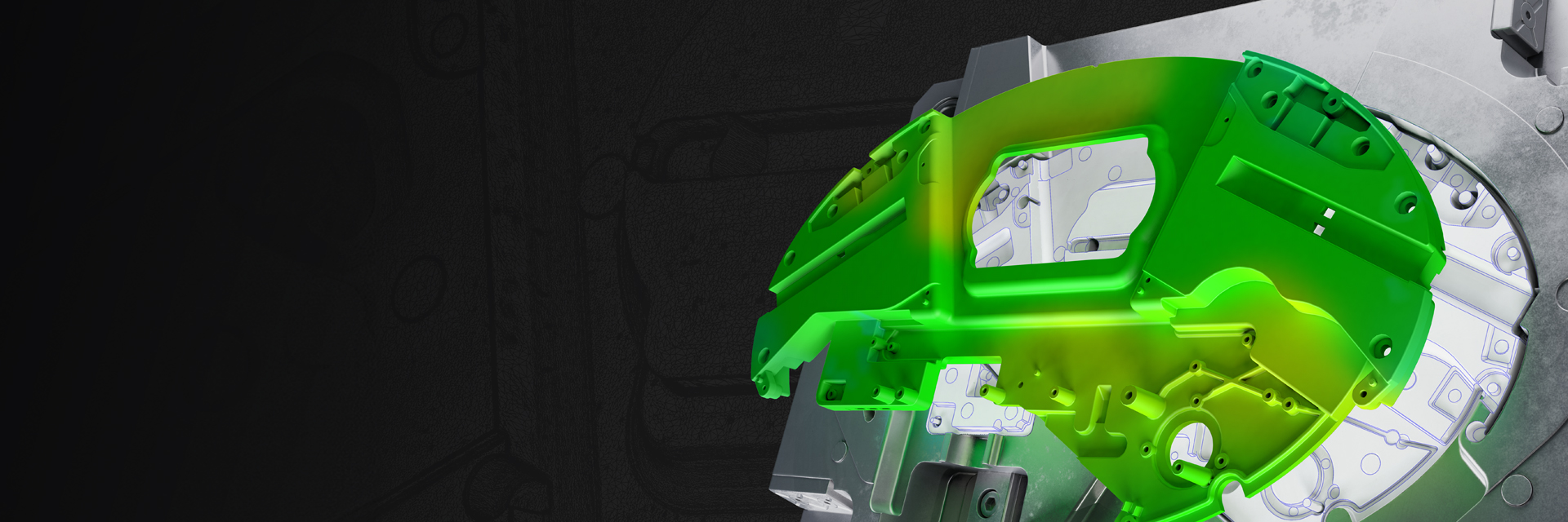
Injection-molded parts shrink and warp during the cooling and demolding stages. In addition, visible sink marks can occur. Simulation tools, design provisions (e.g., taking the shrinkage allowances into account in the development of the injection mold), and crowning are measures employed to prevent the resulting defects on injection-molded parts in advance. But crowning is a significant challenge because the geometric and cosmetic part flaws are due to a variety of influencing factors that are mutually dependent. Even with many years of experience, it is hard to predict the exact behavior of a part. This means that numerous correction loops are necessary until the tool fits perfectly.
ZEISS REVERSE ENGINEERING provides impactful support for injection molding processes as it allows for a significant reduction in correction loops up to the perfect tool. The software suggests only those adjustments that are practically applicable. For example, the software can take into account that corrected tool geometries can be eroded or parts can be demolded.


Correcting 3D printed parts
3D printing processes result in layers of different temperatures, which leads to stresses in the part. The printed part is subject to bending when it is removed from the carrier plate. Bending is usually prevented by various precautions: The printing process is simulated in advance, the printing material, the packaging space, and the carrier plate are pre-heated. Additionally, a subsequent heat treatment is applied in an effort to reduce stresses inside the part. While these measures improve the printing result, they are often not enough to produce parts within the specified tolerances.
This is where ZEISS REVERSE ENGINEERING comes in to provide support and compensate for part defects: Based on the measurement data of the defective printed part, the software optimizes the part’s CAD data. The geometry of the tool is corrected based on the detected deviations.


Sheet metal forming
To be able to manufacture products with consistent quality, solid and reliable deep-drawing tools are needed. The pilot series often reveals that the formed parts have form and position errors. The use of deep-drawing simulations can achieve significant cost reductions in the development of deep-drawing tools. Nevertheless, despite simulations, it often takes forming specialists several attempts until the tool fits. ZEISS REVERSE ENGINEERING helps reduce form and position errors in your deep-drawn parts.